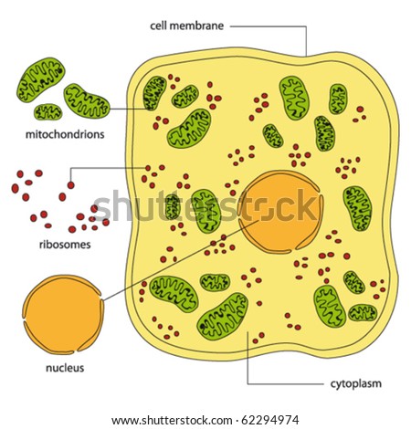
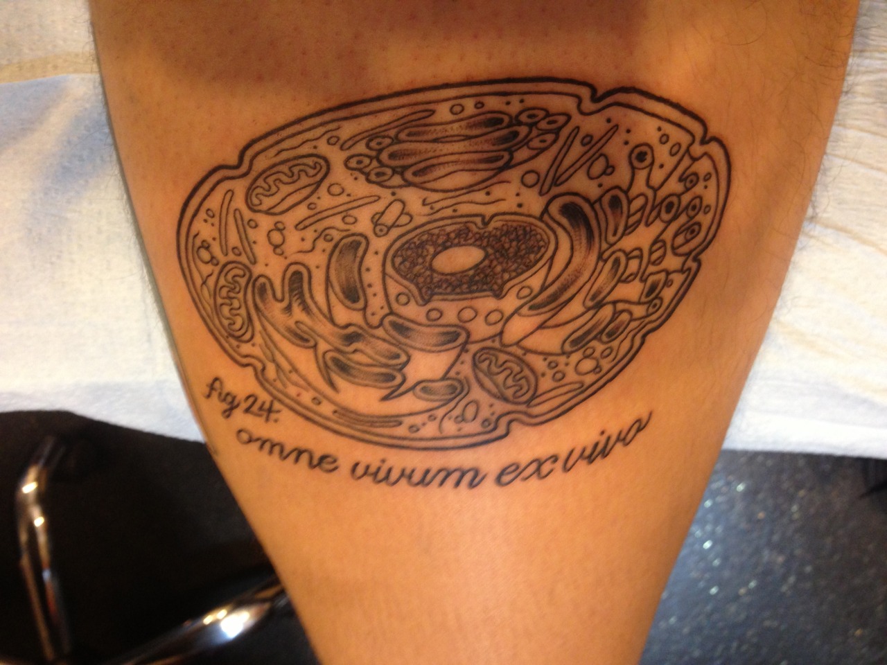
Picture Of A Animal Cell Biography
Source:- Google.com.pk
Shai Shaham § , ed.
The Rockefeller University, New York, NY 10021, USA
This chapter is in WormBook section:
> WormMethods
View/Add Comments
Table of Contents
1. Introduction
2. Visualizing cells and their components
2.1. Differential interference contrast (DIC or Nomarski) microscopy
2.2. Polarized light microscopy (Denise Flaherty and Guy Benian)
2.3. Fluorescence microscopy
2.4. Electron microscopy
3. Protein-protein and protein-DNA interactions
4. Specific methods in C. elegans cell biology
4.1. Endocytosis
4.2. Chromatin cell biology (Györgyi Csankovszki and Barbara Meyer)
4.3. Programmed cell death (Barbara Conradt, Julia Hatzold, Claus Schertl)
5. Embryonic cell culture
6. References
1. Introduction
Although C. elegans is primarily touted for its facile genetics, there has been a burgeoning interest in studying cell biological processes in this organism. Strong genetics (Brenner, 1974; Jorgensen and Mango, 2002), the development of fluorescent protein tags (Chalfie et al., 1994; Yang et al., 1996; Zhang et al., 2004), the availability of RNA interference strategies to disrupt gene function (Fire et al., 1998; Timmons and Fire, 1998), and the ability to perform studies on primary cultures of embryonic cells (Christensen et al., 2002; Zhang et al., 2002), have all led to an increase in the number of cell biological problems addressed in the worm. Furthermore, the transparency of the organism affords a unique opportunity to study the roles of cell biological processes in a living multicellular animal.
A serious obstacle to studying cell biological phenomena in C. elegans is the small size of its cells. However, advances in imaging techniques have allowed faint signals to be significantly amplified, and small structures to be visualized, allowing examination of transport, export, and import processes, as well as examination of cytoskeletal and chromatin structure.
Here we have compiled a set of protocols that broadly fit under the category of Cell Biology. We begin with a brief discussion of various microscopical techniques employed by C. elegans researchers to study aspects of the cell. We then describe methods for studying protein-protein and protein-DNA interactions in C. elegans. We also describe methods used to study specific cell biological problems (e.g. endocytosis, chromatin, programmed cell death). Finally, we conclude this chapter with a discussion of primary embryonic cell culture and its uses.
Contributors of sections or protocols are acknowledged in parentheses following the section or protocol titles. In some cases, protocols are based on previously published work, which is then cited after the protocol title. The on-line format of this chapter should easily allow for revisions and additions to the protocols presented here. Researchers willing to share protocols not presented here or with comments on existing protocols are encouraged to submit these to shaham@rockefeller.edu.
2. Visualizing cells and their components
To study objects we must interact with them. Generally, the technique of interaction is determined by the size of the object. Thus, an object of macroscopic size can be studied by direct contact. However, microscopic objects, such as the cell and its organelles, must be studied with agents of similar or smaller size. Cells in C. elegans are roughly 3–30 microns in diameter, thus, light with wavelength in the visible range (~500 nm) is an ideal interacting agent. The set up of light microscopes affords a resolution that is about half the wavelength of light employed. Thus, light microscopy is useful for examining cells and cellular substructures on the order of 200–300 nm or larger. However, vesicles (often 50 nm in diameter), and other objects of similar or smaller scale cannot be resolved using current setups. Although, in principle, light of very short wavelength (e.g. X-rays) could be used to resolve smaller cellular structures, such light is too energetic, damaging the cell upon contact. In addition, lenses to focus high energy photons do not exist. High resolution can be obtained using electron microscopy. Moving electrons in an electron microscope possess wavelengths on the order of 0.3 nm. Using an electron microscope, the electrons can be used to form resolved images of cellular structures of about 3 nm in size.
2.1. Differential interference contrast (DIC or Nomarski) microscopy
Visible light can be used to examine C. elegans, however, in general, bright field and phase-contrast microscopy offers little contrast- making cells and their major components difficult to see. DIC microscopy, however, allows high contrast images to be formed, and is ideal for examining nuclei, nucleoli, and granular structures within C. elegans cells (Sulston and Horvitz, 1977; Sulston et al., 1983). In DIC microscopy light passes through a plane polarizer. The resulting polarized light is split into two components using a prism. These components interact with the sample, and are combined above the objective using a second prism. Finally, the transmitted light passes through an analyzer (essentially a polarizer that is polarized at 90 degrees with respect to the original plane of polarization) and on to the observer. The interaction of polarized light with the sample changes its plane of polarization. Thus, only light whose polarization is changed by the sample will be detected by the observer. In this way, highly contrasted images are formed. It should be remembered that shadowing effects seen using DIC microscopy do not reflect three-dimensional features of the sample. Rather, they reflect the ability of the specimen to interact with polarized light. Current microscopes allow the use of a 100X objective with DIC, giving high magnification and resolution. Some microscopes are equipped with additional lenses, however, these do not afford better resolution.
A protocol for mounting C. elegans for observation using DIC microscopy is presented below. This protocol can be used to mount animals for all microscopic techniques utilizing a compound microscope.
Protocol 1: Mounting animals for observation with DIC optics (Monica Driscoll)
1. Preparation of Agar Pads:
a. Materials
5% agar solution in water, melted and kept molten by placing the tube in a heat block at 65°C
Pasteur pipette and bulb
2 glass slides with pieces of labeling tape (for example, Fisher #11-880-5-D) taped over both ends to serve as spacers
2 clean glass slides
b. Preparation of Pads (See Figure 1):
figure 1
Figure 1. Preparing agar pads (Monica Driscoll).
Place the two taped slides with a clean slide sandwiched between them on a flat surface. Using the Pasteur pipette, place a drop of agar onto the clean slide. Cover the agar with another clean slide placed on top of the three slides in a perpendicular fashion. Press gently so the agar drop is flattened to a circle about 0.4 mm thick (the thickness of the tape spacers). Avoid getting bubbles in the agar since worms will get stuck in them. After the agar solidifies, gently pull out the taped slides, then separate the remaining two slides by sliding one relative to the other. The agar pad should adhere to one of the slides (usually the bottom one). Rest the slide, agar side up, on the bench top.
Note: The agar pad should be prepared just before use so that it does not dry out. Alternatively, once you pull out the taped slides, you can wrap the cross shaped slide-agar-slide in a piece of Saran wrap. This way you can keep the pad moist for a couple of hours.
2. Mounting Live Animals:
Place a 1–2 ul drop of M9 containing 10–25 mM sodium azide (NaN3) onto the center of the agar pad. NaN3 anesthetizes the worms so that they will not move. The agar pad can also be prepared with anaesthetic included for a final concentration of 2–10 mM NaN3 in the agar, instead of in the drop. This generally results in faster anesthetic action. If live worms are needed, NaN3 can be omitted and bacteria can be added to the drop to allow the worms to feed with little motion.
Transfer animals to be observed into the drop. Animals can be transferred using a worm pick or an eyebrow hair fastened to a toothpick with wood glue or clear nail polish. When the hair or pick is moved into the drop, animals float off easily. Alternatively, animals can be spun down in M9 in an eppendorf tube at 1200–1500 rpm with slow acceleration/deceleration. After the supernatant is discarded, the animals are suspended in 10 ul M9-NaN3. 2–3 ul of the solution with the animals can then be transferred to the pad.
Gently lay a coverslip over the animals. Most animals will lie on their left or right sides. Embryos also generally assume stereotypic orientations on agar pads. Between the 4-cell stage and 100–150 minutes the embryos display either the left or right sides. At gastrulation (150 min) they turn from left to dorsal or from right to ventral. At 350–400 minutes they return to display left or right sides (Sulston et al., 1983).
Animals will stop moving within a minute or two. Animals in sodium azide can recover following incubation in sodium azide of one-hour or less.
2.2. Polarized light microscopy (Denise Flaherty and Guy Benian)
Polarized light can be used to examine repeated or crystalline structures. In a manner similar to DIC, plane polarized light that passes through a specimen will interact with the specimen and change its plane of polarization, allowing light to be detected through an analyzer located above the specimen and oriented at 90 degrees to the initial plane of polarization (for a more complete description see http://www.microscopyu.com/articles/polarized/ polarizedintro.html).
The muscles used for locomotion in C. elegans reside in the body wall. In the adult, there are 95 spindle shaped cells divided among four quadrants just underlying a basement membrane, hypodermis and cuticle. In each quadrant, the cells are arranged in interlocking pairs. In these muscle cells, myofilaments form a lattice that is restricted to a narrow zone of ~1.5 microns, just underlying the basement membrane and hypodermis. By polarized light microscopy, obvious striations are seen; bright (“birefringent”) A-bands alternate with dark I-bands; each I-band contains a row of dense bodies, which are the analogs of Z-discs of vertebrate striated muscle (Figure 2). Because the striations lie at a slightly oblique angle with respect to the long axis of the worm, this muscle is called “obliquely striated”. Polarized light is also useful for evaluating the second largest set of muscles, those in the pharynx. Below we present a protocol for observing C. elegans muscle using polarized light.
Protocol 2: Observing C. elegans muscle using polarized light (Denise Flaherty and Guy Benian)
Materials and Equipment
1. Healthy worms
2. Light microscope (not inverted) with:
light source
strain free objectives
condenser appropriate for bright-field and differential interference contrast microscopy (often labeled H/DIC)
an analyzer slider
A rotating stage. This would not be necessary if worms had an obliging habit of lying down on the slide, stick straight, at a 45° angle within the field of view.
Method
Pick one to several adult animals onto a clean glass slide (avoid dust) containing an 18ul drop of M9 buffer. Take care to pick up as little bacteria as possible, as it could obscure the view. It is also often customary to add sodium azide to a final concentration of 20 mM in order to slow the movement of the animal for imaging.
Next, cover the animal with a number 1 coverglass, 22 by 40mm, and view the animal under the microscope using the following procedure:
Be sure that the analyzer slider is in place
Set the index of the condenser to “H/DIC”
Move any color or gray filters out of the way
For microscopes with a rotating polarizer, set the rotating polarizer lever on the condenser to 0°.
Find the animal on the slide using a low power objective such as 10X.
Once the animal has been found, place it in the center of the field of view.
Carefully move up to a higher magnification objective such as 40X.
Get the animal into focus then close down the luminous field diaphragm so that the edges of the opening are in the field of view.
Change the height of the condenser until the edges of the opening are in crisp focus. Then use the condenser centering screws to center the opening in the field of view.
Open the luminous field diaphragm wide enough so that the edges go just beyond the field of view.
Rotate the stage until the muscle striations are most clearly seen. (This occurs when the striations are at a 45° angle with respect to the field of view).
Change the level of light in the field by using the light source dial and/or the condenser diaphragm.
Notes
getting the right “balance” of light is the key to successful polarized light microscopy. As the light from the light source is increased and the light coming through the condenser is decreased, stronger contrast will be achieved. Sometimes this contrast is too sharp, making the muscle look “grainy”. If this is the case, begin to reduce the light from the light source and increase the light coming through the condenser. If this is done too much, there will not be enough contrast. Tweak each source of light carefully until the desired polarized light is achieved.
Worms that are healthy adults without many developing embryos are the best for polarized light microscopy due to the interference of these embryos over a quadrant of body wall muscle. Similarly, when a quadrant of body wall muscle happens to lie over the reflected arm of the gonad, this is advantageous, since the gonad acts as an empty window through which the muscle can be seen. Skilled practitioners of polarized light microscopy are able to gently roll the worm under the coverslip in order to achieve this effect
Picture Of A Animal Cell Animal Cell Model Diagram Project Parts Structure Labeled Coloring and Plant Cell Organelles Cake
Picture Of A Animal Cell Animal Cell Model Diagram Project Parts Structure Labeled Coloring and Plant Cell Organelles Cake

Picture Of A Animal Cell Animal Cell Model Diagram Project Parts Structure Labeled Coloring and Plant Cell Organelles Cake

Picture Of A Animal Cell Animal Cell Model Diagram Project Parts Structure Labeled Coloring and Plant Cell Organelles Cake

Picture Of A Animal Cell Animal Cell Model Diagram Project Parts Structure Labeled Coloring and Plant Cell Organelles Cake

Picture Of A Animal Cell Animal Cell Model Diagram Project Parts Structure Labeled Coloring and Plant Cell Organelles Cake

Picture Of A Animal Cell Animal Cell Model Diagram Project Parts Structure Labeled Coloring and Plant Cell Organelles Cake

Picture Of A Animal Cell Animal Cell Model Diagram Project Parts Structure Labeled Coloring and Plant Cell Organelles Cake

Picture Of A Animal Cell Animal Cell Model Diagram Project Parts Structure Labeled Coloring and Plant Cell Organelles Cake

Picture Of A Animal Cell Animal Cell Model Diagram Project Parts Structure Labeled Coloring and Plant Cell Organelles Cake
Picture Of A Animal Cell Animal Cell Model Diagram Project Parts Structure Labeled Coloring and Plant Cell Organelles Cake
No comments:
Post a Comment